Who Let the Magic Smoke Out?
Spoiler alert: It was me.
The goal was to test out both the PiBorg UltraBorg and Sunfounder Servo Driver boards and ensure the Pi could talk to them and they could be used to drive both the Servos and Ultrasonics. It didn’t quite go to plan. Unless the plan was to burst some AA batteries and let some magic smoke out of the servo driver board. To be clear: it wasn’t.
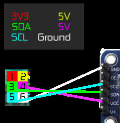
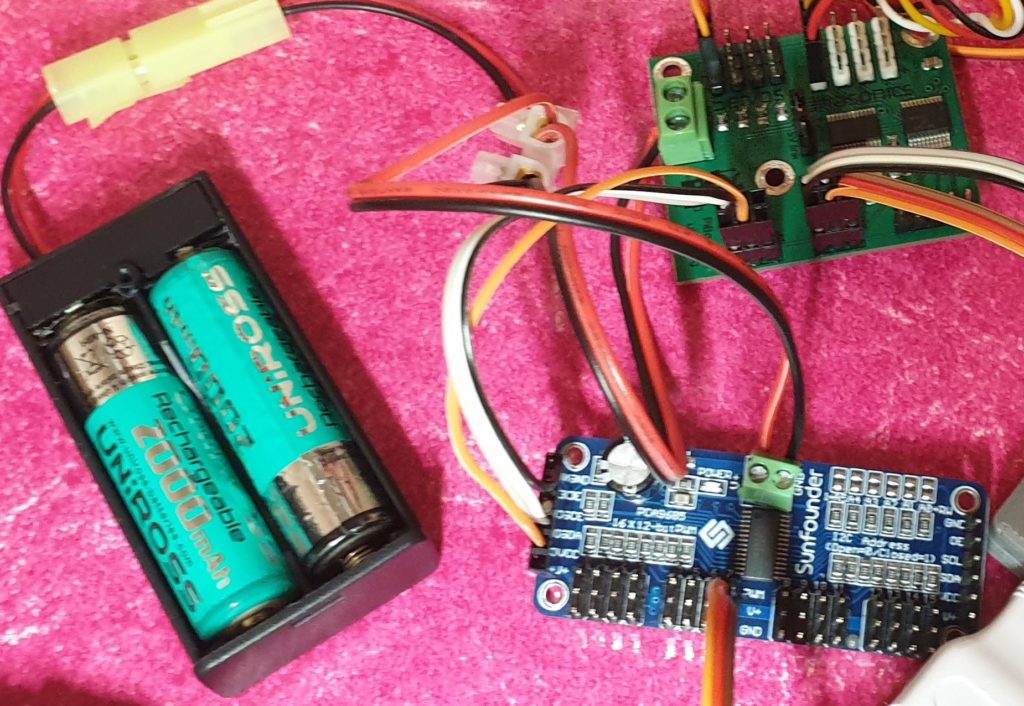
I created a 2×3 header from the pi to the UltraBorg with all pins connected as shown in the image. As I was expecting to have to use a separate power supply as the test included a servo I removed the jumper connector on the UltraBorg.
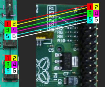

As both devices are I2C, I then created a cable with a 2×3 connector on one end and a 1×6 on the other which allowed the pass through pins on the UltraBorg to connect to the servo driver.
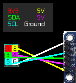
It was at this point I noted the VCC and V+ and didn’t pause to think of the significance. I did think to myself that it was odd the board didn’t contain a jumper to select the power source for the servos. It didn’t help that I was struggling to find any details on the Sunfounder board as the link to the wiki from the produce page returned a 404. I have subsequently found a working link here.
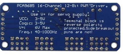
In fairness the back of the board does highlight that the V+ should be used for the servo supply and I had in essence connected the +5v from the pi to it instead.
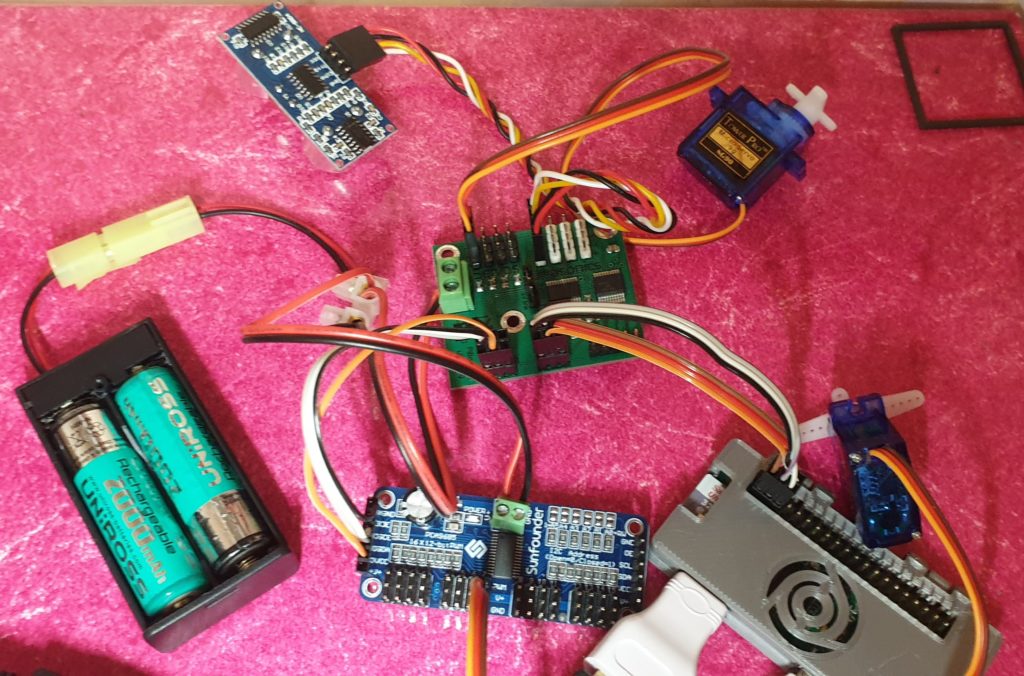
So when I added a 2xAA battery pack and connected it to the power screw terminals for both boards I suspect I was attempting to charge the batteries in the holder. (The batteries in the image are not the ones I attempted to explode).
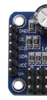
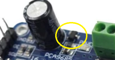
I noticed something was wrong when I heard fizzing. The batteries I was using were old so I initially assumed they had just succumbed to old age. Just before I rapidly disconnected the battery pack I noticed a small amount of “magic smoke” coming from the highlighted component in the image on the right.
That looks like a power regulator which potentially had two separate power sources going through it. Without looking at a wiring diagram for the board I’m not sure which of the failure cases were being exercised…
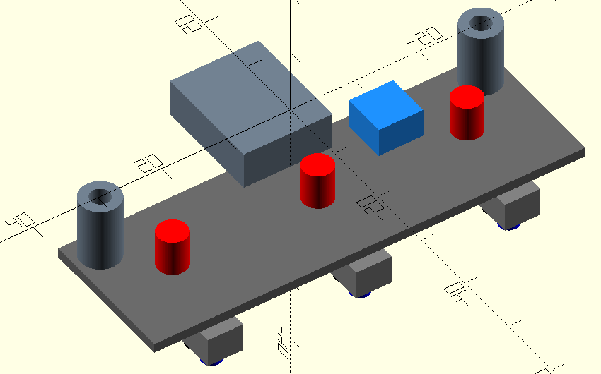
The updated wiring removes the additional 5v link between pin2 and V+ on the servo board. This should now mean the servo’s are only powered by the external batteries and there is no link to the Pi’s 5v. It remains to be seen if the regular has suffered any major damage, but when connected to the pi (with the V+ link removed) it is still visible as an I2C device.
I will put up another post when I have had chance to test both boards properly.