How to mount a Line Follower – The Planning and Designing Stages.
We need to mount the line follower on the base on the robot in the centre. After some quick research I found that, for it (the line follower) to work at its optimum, the line follower needs to be mounted REALLY close to the ground.
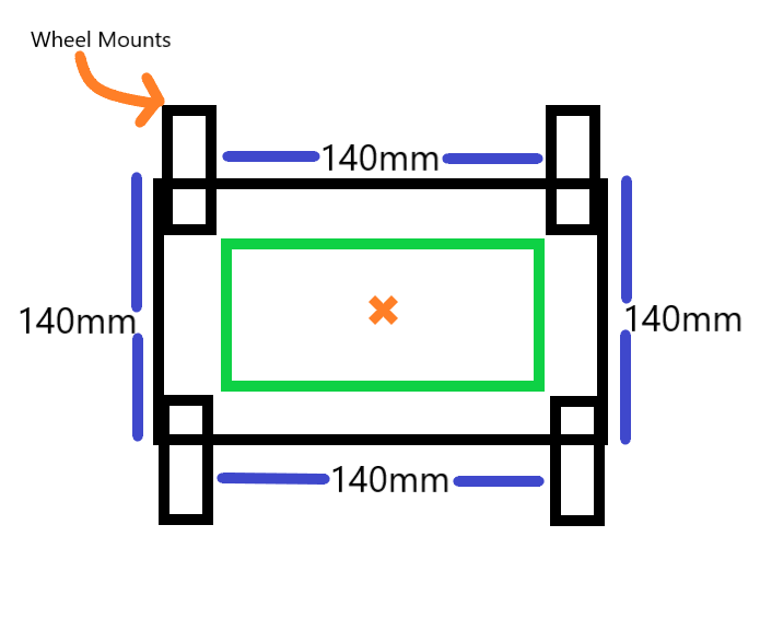
Measurements of the robot:
- From the inside of the wheel mounts at either end, there is a gap of 140mm.
- The width of the whole robot is 140mm.
Measurements for the line follower:
- Length = 67.08mm
- Width = 27.5mm
- Depth (Thickness) = 2.3mm
- Mounting Hole Sizing:
- Diameter: 3.3mm
- Hole is 2mm from edge of the line follower board.
- Gap between LEDs = 17.78mm
We have 2 ideas for how the line follower could be mounted:
- Directly onto the robot.
- Onto a base that is already mounted on the robot.
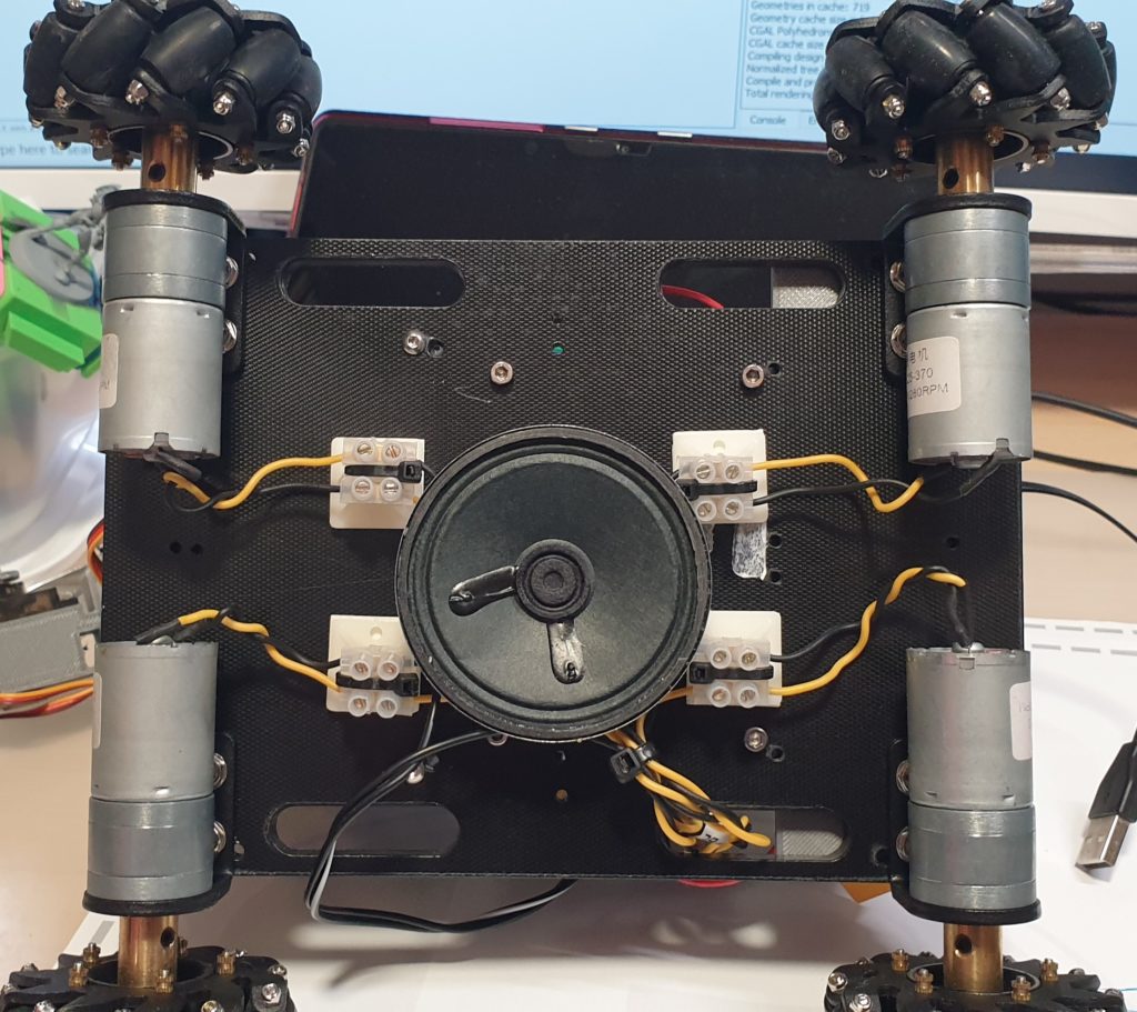
An issue: How do we feed the cables through?
Solution: There are already gaps along the side of the robot that can utilised to feed cables through.
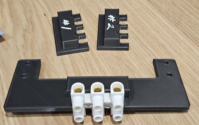
We will most likely relocate the speaker to a place that it can be more securely fastened on.
Related Information:
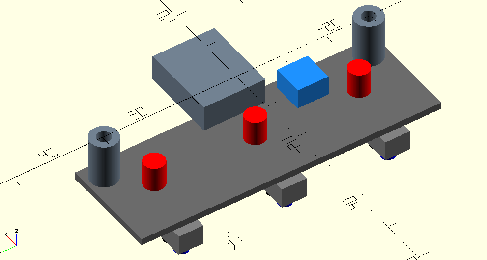
This is a simplified Line Follower created using OpenSCAD.
The Line Follower is going to take the place of the speaker (that we used to make lemming noises).