Mounting a Pi 3 Board
The existing Pi Zero was struggling to have enough power on the USB port to drive the remote control dongle, so needed to be replaced with a slightly more capable Pi 3.
The existing stack system is working well on the test robot, so the goal here is to replace the top stack with a Pi 3 version.
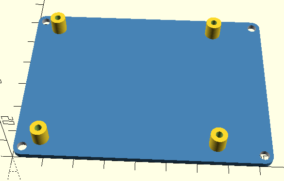
As before this started with an OpenSCAD file to produce 6mm M2.5 posts in the correct positions for the Pi 3.
Luckily there are plenty of technical diagrams available giving the exact measurements.
But to sanity check a Pi 3 reference model was found on Thingiverse which could be used the sanity check the fit – which it did.
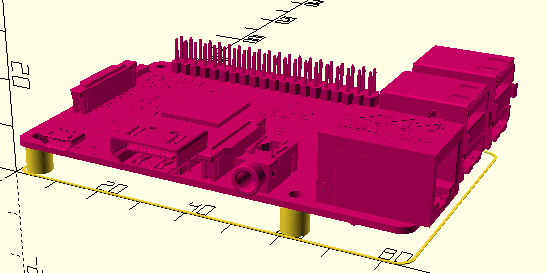
Using the MDD10A OpenSCAD file previously created and taking just the bare board and screw holes was a good start.
The only issue with a Pi 3 is that it will overhang the board slightly, and two of the screws holes for the stack board are slightly covered by the Pi.
Despite these limitations it seemed ok, so was printed.
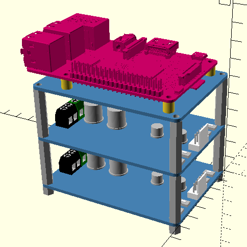
Fully built it should look like this:
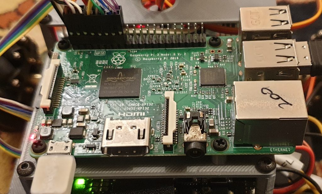
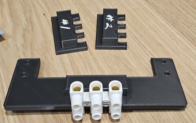
Printed and mounted!